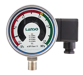
Density of gas is an important working structure of high-pressure equipment. If the required density of gas does not exist, the safe operation of the current working environment cannot be guaranteed. This is why SF6 gas density monitoring is an essential part of providing a safe and reliable working environment.
Ⅰ. How does the SF6 gas density monitor work?
The density of gas is usually determined indirectly by the air pressure using a pressure gauge or pressure sensor. Since the pressure in a confined space varies greatly with temperature, such equipment requires temperature compensation. The SF6 gas density monitor provides this compensation and is operated via electrical switch contacts. Once the gas level reaches an unacceptable level, the electrical contact switch is triggered and a warning is sent to the operator.
Ⅱ. SF6 gas density monitoring
The portable SF6 gas density monitor is a reliable and economical way to monitor SF6 gas density and leakage in a wide temperature range. The temperature-compensated pressure switch will automatically adjust its settings to adapt to the temperature changes of all SF6 gas density levels (including mixed gases). These switches are mainly used to measure the density of SF6 in high-voltage circuit breakers.
Ⅲ. How to eliminate the spark of SF6 gas density relay contacts?
(1) The current of the SF6 density relay contacts is very small, and there is almost no arc between the contacts. The spark at the contact is attributed to the inductance in the contact circuit. When the contact is open, there will be an overvoltage on the inductor. Overvoltage and power supply voltage are located on the contact gap and discharge through the gap just separated. Due to energy limitations, spark discharge is the only phenomenon. The energy displacement and conversion in the capacitance and inductance existing between the contacts cause the spark discharge to flicker and become a high-frequency signal.
In addition, spark discharge can damage the contacts and shorten the service life, so sparks must be eliminated.
(2) The following are two effective spark elimination methods:
1. The working principle of SF6 relay is to make the energy in the inductor pass through RC (resistance capacitance) instead of through contacts.
2. The second working principle of SF6 relay is that when the contact is disconnected, the load through the diode will consume energy.
3. You can choose a method in practice. Please pay attention to choosing RC with appropriate parameters, and these parameters are mainly determined through experiments. Generally, RC can be selected based on load current 1a/1 microfarad. When using a diode, the anode and cathode should be connected correctly.
If the load of the SF6 relay contact cannot meet the application requirements, it can be handled by several pairs of parallel contacts. Please adjust the contact before use to make the synchronization meet the requirements. The best way is to choose a central relay or contactor to increase the load of the contacts.


