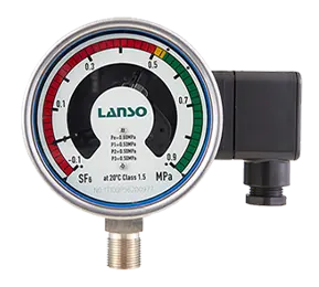
SF6 Relay is a commonly used protective and control element in electrical systems. Outdoor GIS substations may experience various adverse conditions such as high humidity and rain, which can lead to condensation, water seepage, and other issues, increasing the occurrence of contact misoperation, failure, and abnormal conduction. This increases the pressure of power system operation and poses a certain threat to the safety of power system operation. It is necessary to identify common types of faults during the operation of SF6 Relays, analyze their causes, and develop feasible solutions.
SF6 Gas Leakage and Handling Measures
Fault Analysis
SF6 gas has extremely stable chemical properties, and pure SF6 is non-toxic and harmless. However, the products formed after chemical reactions are toxic or highly toxic. When there is a large current passing through and the circuit is disconnected, arcing discharge occurs, resulting in the generation of toxic sulfur low-fluoride compounds.
The reactivity of this substance is relatively strong. If water vapor lingers around or the oxygen concentration reaches a certain level, it will react with electrode materials and moisture to form complex compounds. Additionally, SF6 gas itself has a negative impact on the environment. Studies have shown that one molecule of SF6 gas has a greenhouse effect that is more than 250,000 times stronger than one molecule of CO2. Furthermore, if SF6 gas is released into the atmosphere, its lifespan can be extended to approximately 3,400 years. Although the concentration of SF6 gas in the air is significantly lower than that of CO2, it still contributes to the formation and development of the greenhouse effect.
Methods of Handling
(1) Inspect the isolation valve and check valve for airtightness before disassembling the meter for calibration.
(2) Ensure close connection between the calibration equipment and the SF6 relay. Before conducting the calibration, apply a certain pressure to the SF6 relay and visually observe if the pressure indicator does not decrease after a period of time. This indicates that there is no leakage and a compact connection. Then proceed with the calibration operation.
(3) It is recommended to use calibration facilities with SF6 gas recovery function. After the overall calibration work is completed, the SF6 gas stored in the facilities should be completely recovered to ensure no leakage of SF6 gas in the facilities.
(4) After the calibration work is completed, promptly replace the check valve or meter head to achieve sealing treatment for the rubber ring. The new and original rubber rings should have uniformity in terms of material, pipe diameter, and specifications. Before application, evenly apply an appropriate amount of Vaseline.
(5) Because the circuit breaker generates noticeable oscillations during the opening and closing operations, it is necessary to strengthen the inspection and evaluation of the reliability of the meter head position for SF6 relays installed in the circuit breaker mechanism box.
Excessive Moisture in SF6 Gas and its Treatment Methods
Causes
During the installation of SF6 equipment, due to insufficient baking time or failure to meet relevant specifications, some internal moisture may diffuse internally and externally after assembly, resulting in an increase in moisture content in the SF6 gas beyond the standard.
Infiltration of moisture molecules in the air. Due to the presence of pressure difference, moisture molecules in the air can penetrate through weak sealing points of the SF6 equipment into the interior.
Treatments
Open the arc-extinguishing chamber and replace the adsorbent.
The replacement and loading of the adsorbent should be done in as short a time as possible to avoid excessive adsorption of moisture.
When filling SF6 gas, the gas cylinder should be placed upside down so that the valve mouth is lower than the bottle body. This allows for liquid-phase filling to reduce the entry of moisture into the circuit breaker.


